3D printed enclosure for the Raspberry Pi All Sky Camera
2020 Nov 22 - Brian Kloppenborg
This is the second post in a series which discusses the development of an open-source all sky camera built on top of the Raspberry Pi and Raspberry Pi HQ camera. The previous post determined the magnitude limit and general capability restrictions of the setup. In this post, I’ll describe the design of a 3D printable enclosure for the camera.
Design
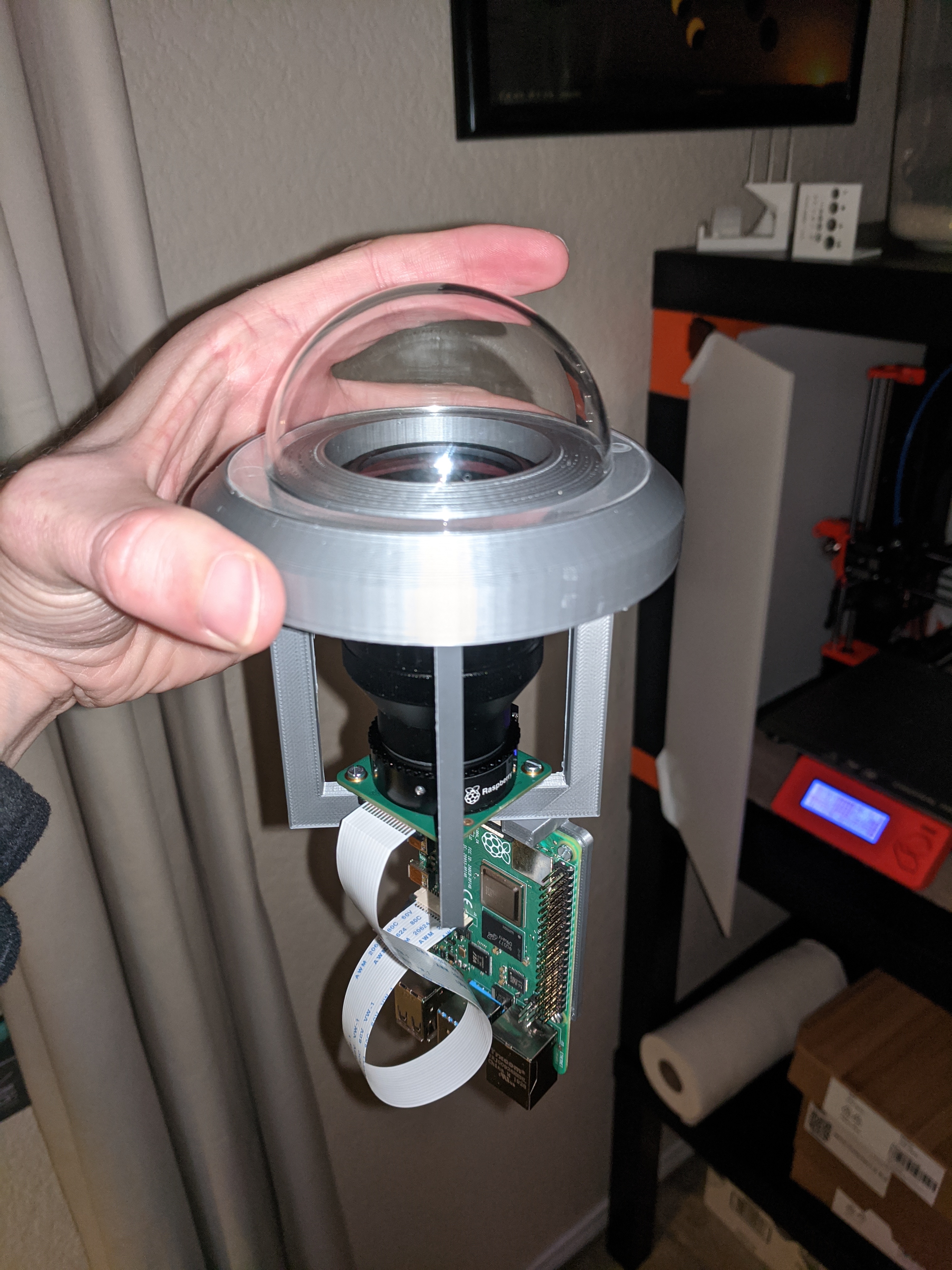
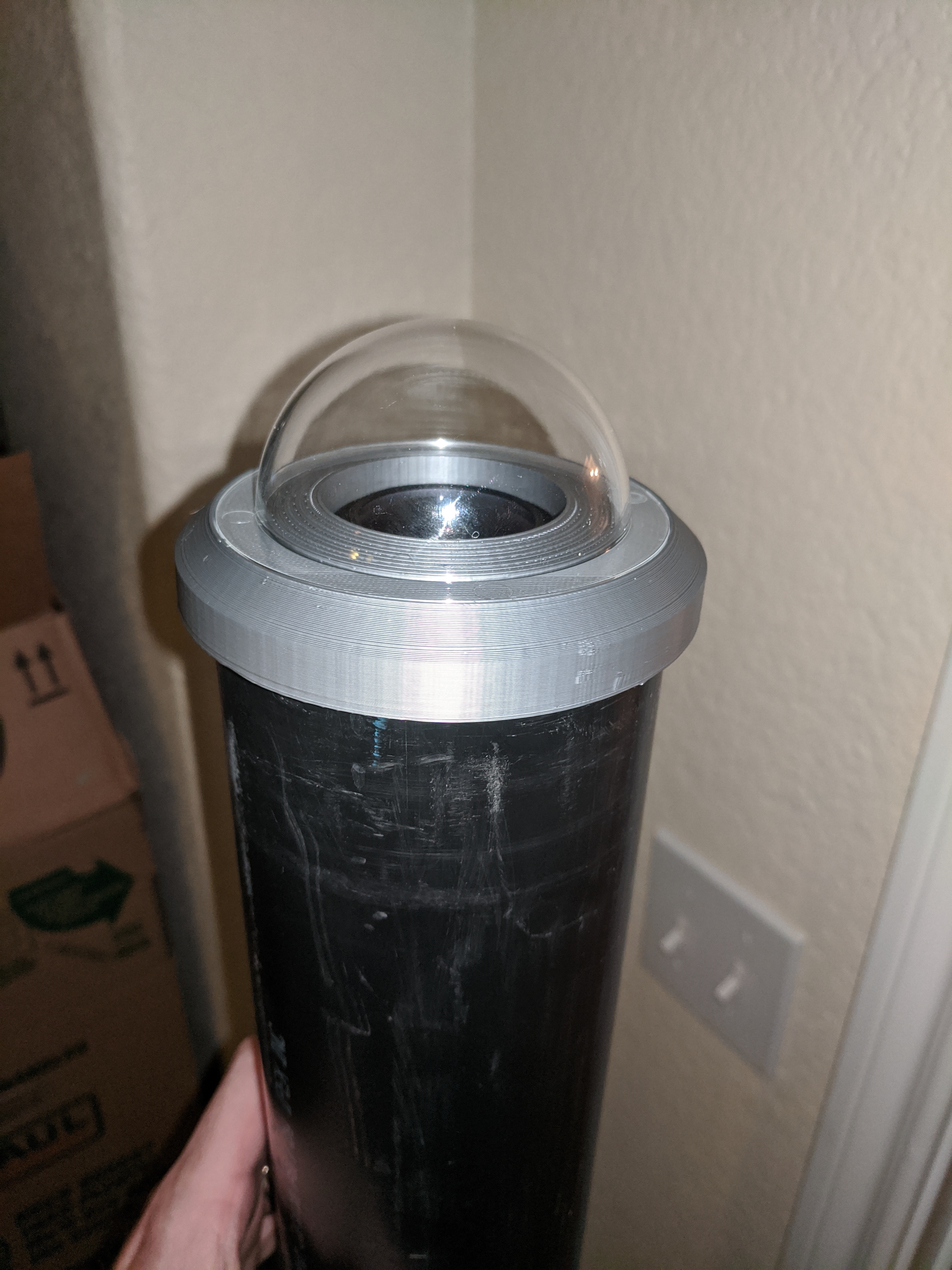
After drawing up several ideas, I settled on a relatively simple design that encases the Raspberry Pi, HQ camera, and associated lens into a section of ABS plastic pipe as shown below:
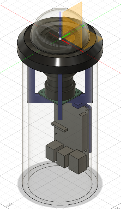
They key difference in this design over other approaches I’ve seen online is that everything is supported by the flange on the top. This lets you easily remove everything in one shot when maintenance needs to be performed. Because of this design choice, the flange is designed to shed water. The entire top is sloped, including the portion under the acrylic dome. The bottom edge of the flange has an integrated drip edge. Note that I have NOT tested this yet, but the idea at least seems like it should work.
In order to maximize space for sensors and other accessories within the tube, I shifted the Raspberry Pi to one side. While this frees up 2-3 cm of space, it causes the USB-C connector to be blocked. Thus, if you use this design, you must inject 5V 3A power into the board using either the PoE hat or a dedicated power supply connected to pins 2/4 (positive) and 6 (negative) of the 40 pin connector.
Note that I have yet to design a bottom for the enclosure as I haven’t figured out precisely how I want to connect to the unit. Fortunately, this should be relatively easy to do.
Parts, Cost, and Construction
Part list and cost
To construct this kit you will need:
| Part | Quantity | Price (USD) |
|---|---|---|
| Raspberry Pi 4 | 1 | 55.00 |
| Raspberry Pi HQ Camera | 1 | 55.00 |
| Arducam 2.8 - 15 mm varifocal lens | 1 | 65.00 |
| 5 V 3 A power supply | 1 | 10.00 |
| 70 mm acrylic dome | 1 | 9.00 |
| 3" Black ABS DWV pipe | 1 | 10.00 |
| 3D printed parts (see below) | 1 | 2.00 |
| M2.5 x 8 mm screws | 4 | 1.20 |
| M2.5 x 18 mm screws | 4 | 1.20 |
| M2.5 x 4 mm screws | 6 | 1.80 |
| M2.5 nuts | 8 | 0.40 |
| Total | – | 210.60 |
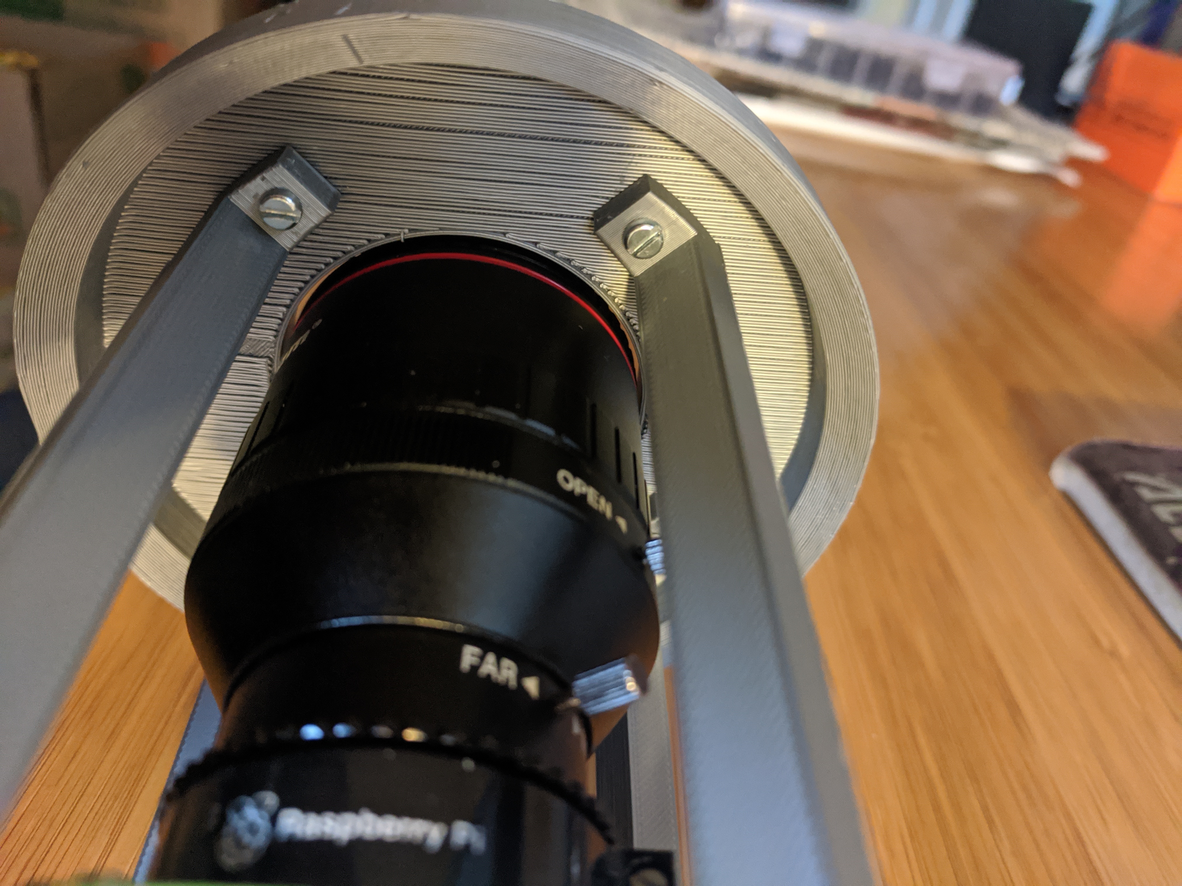
Ideally you should use socket screws. I found assembly difficult with the straight slot screws shown in the photos below.
Printing
Start by printing the 3D printed parts. The parts consist of the top flange, two large U-shaped parts that form the camera support assembly, one tray for the Raspberry Pi, and a “spine” for the tray. As can be seen below, the all fit nicely on the bed of my Prusa MK3S 3D printer:

Ideally you should finish these prints with sanding and paint to make them water resistant. As this is a prototype unit, I left mine unfinished.
Assembly
I forgot to take photos during the assembly process, so I’ll describe the major steps:
- Assemble the two U-shaped parts to form the camera support assembly.
- Attached the “spine” to the Raspberry Pi support structure using two of the M2.5 x 8 mm screws.
- Attach the Raspberry Pi to the Raspberry Pi support structure using M2.5 x 4 mm screws and 4 nuts.
- Attach the lens to the HQ Camera.
- Set the camera into the camera assembly.
- Attach the camera and Raspberry Pi support structure to the camera assembly using all four of the 2.5 x 20 mm screws and four nuts. Start with the two holes next to the ribbon cable.
- Attach the camera support assembly to the flange using the remaining M2.5 x 8 mm screws.
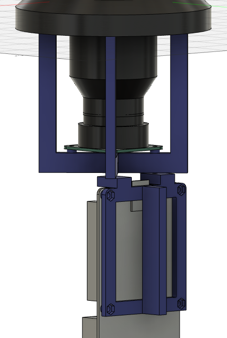
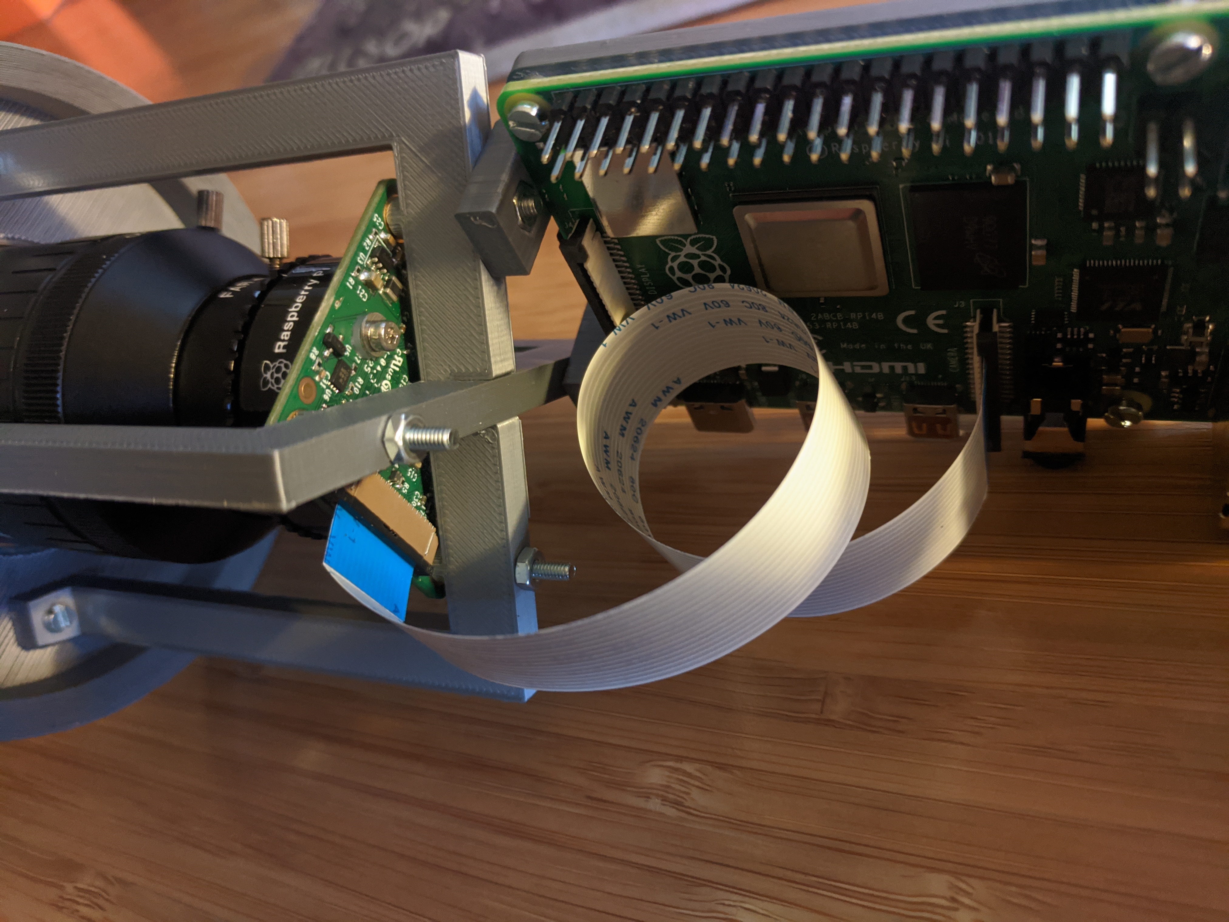
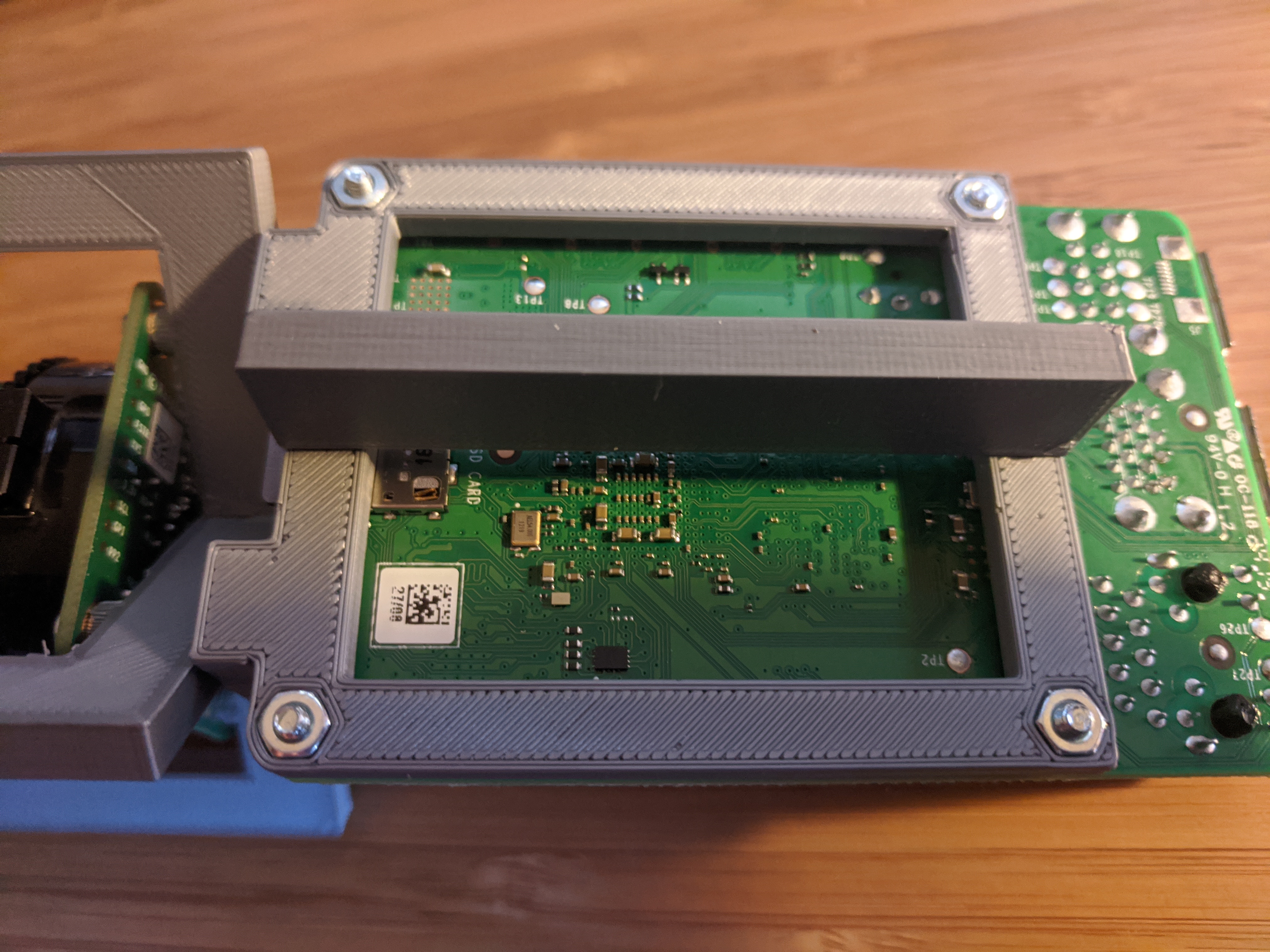
Below are some detailed photos to show you how the screws fit together. Notice that the ribbon cable can be looped to fit nicely within the tube.
After everything is assembled, you can attach the 70 mm acrylic dome to the top flange. Ideally you would seal this with some silicon caulking or similar, but as this is an experimental unit, I just used a few dabs of hot glue.
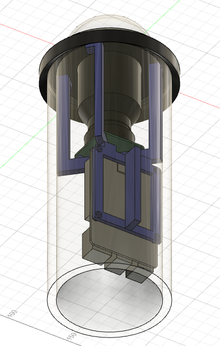
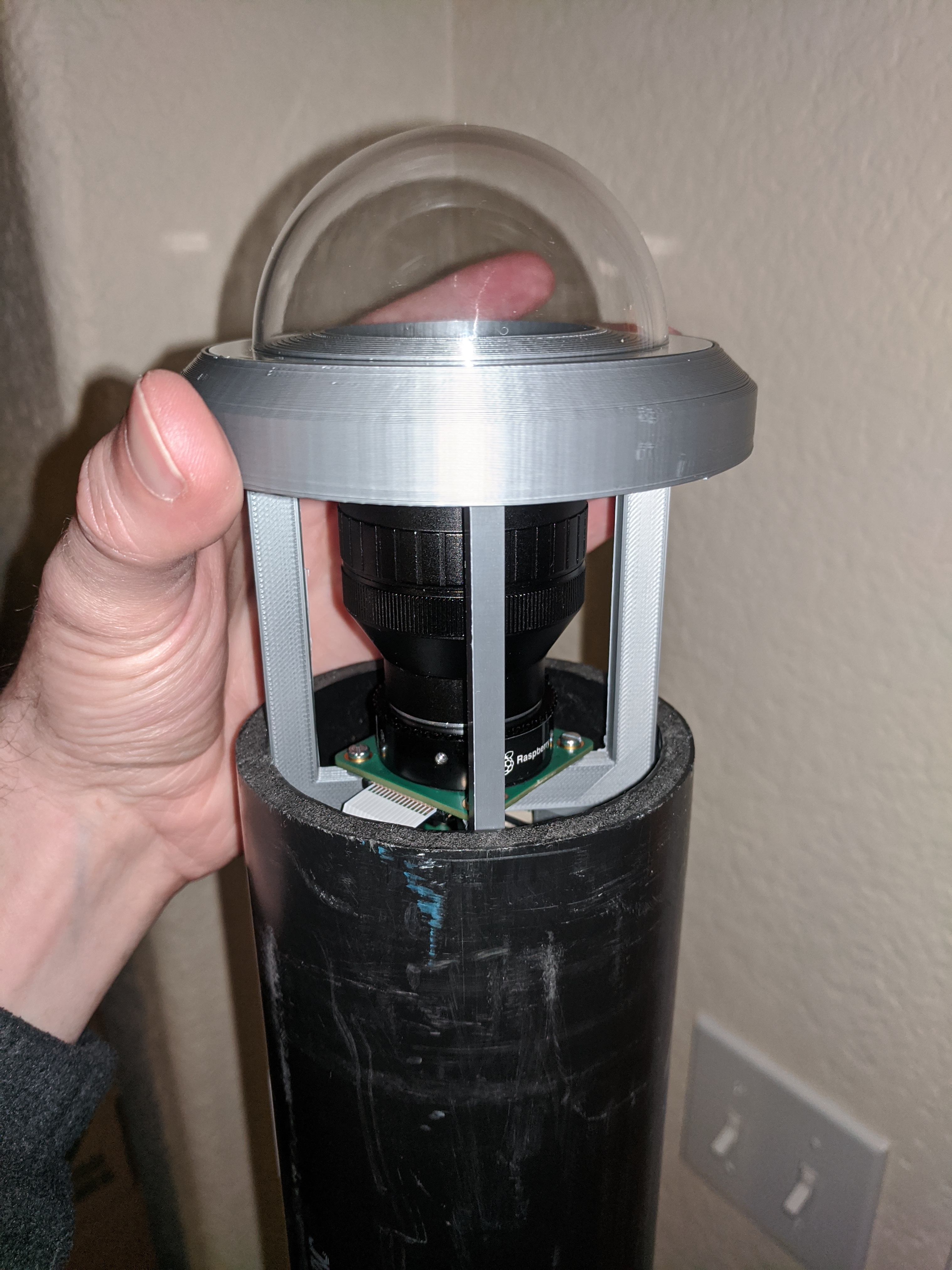
Once complete the unit should slip nicely into the 3" ABS tube as shown below.
Power
In my unit I’ve attached 5V 3A power directly to the relevant pins in the 40-pin header and ran the power cable behind the Raspberry Pi support structure. In the future I may use the PoE hat instead.
Downloads
Note: All 3D printed parts are Copyright 2020 Brian Kloppenborg. All rights reserved.
Parts in Prusa Slicr
STL files:
- Top flange
- Raspberry Pi support structure
- Raspberry Pi support spine
- Camera support part A
- Camera support part B
Conclusion and next steps
In the above post, I discussed the design and construction of a 3D printed enclosure for the Raspberry Pi all sky camera. With the feasibility established and the unit now able to be installed outside, my next post will discuss the requirements I wish to levy against this system.