Getting Started with the ESP 8266 (ESP-12e)
2016 Aug 02 - Brian Kloppenborg
Several months ago we purchased an Arduino Starter Kit from OddWires to experiment with during downtime. We’ve used it for several fun projects, but not much more because it didn’t have Internet access. After talking with some friends at ArrayFire, we decided to purchase an ESP8266 for some wifi-enabled microcontroller fun.
For those of you who don’t know, the ESP8266, an obnoxiously inexpensive microcontroller with built-in 802.11b/g WiFi. There isn’t a whole lot of documentation providing detailed information about its capabilities (save one extremely useful free e-Book by Neil Kolban) beyond technical specifications published by the manufacturer. As the e-book was slightly out of date (and a little too verbose for my liking), I’ve decided to chronicle a few things about the platform here as a quick-start guide for others looking into the device.
Background
The ESP8266 is a microcontroller built by Espressif Systems that has WiFi built in. Although the microcontroller is only produced by one company, there are a variety of board styles and a multitude of vendors selling development boards. To date, the most important variants are the ESP-1 (the original release) and the ESP-12E (the latest version as of this writing). The main differentiation between these versions was not the microprocessor (this has remained essentially unchanged), but instead the number of ports exposed to the user. For example, the ESP-1 has a total of eight pins connected to user-reachable headers (two of which were used for power), whereas the ESP-12E has 22 pins. As far as I am aware, all esp8266 boards use the ESP8266EX module whose (English) datasheet can be found linked to later in this post.
You can do some really awesome things with the ESP8266, for example, the Analog to Digital Converter (ADC) can be leveraged along with websockets to make a web-enabled oscilliscope.
The ESP8266 has the following specifications:
| Property | Description |
|---|---|
| Voltage | 3.3 V (3.0 - 3.6 V tolerated) |
| Current | 10 uA - 500 mA (64 mA average) |
| Processor | Tensilica L106 32 bit |
| Processor Clock | 80-160MHz |
| RAM | 32K + 80K (explained below) |
| Storage | Flash memory, 16MB max (512 K - 4 MB often provided) |
| GPIOs | 17 (multiplexed with other functions) |
| ADC | 1 (10 bit) |
| WiFi | 802.11 support b/g/n/d/e/i/k/r |
| TCP Connections | Max: 5 concurrent |
Depending on the particular board on which your ESP8266 microcontroller is mounted, not all of these features may be exposed
ESP8266 Boards
There are a variety of ways to get your hands on an ESP8266 including:
- Raw boards ~ $3 - Search eBay, Mouser, or similar electronics websites. This is probably not what you want when learning how to use the board.
- Adafruit HUZZAH $8-10
- NodeMCU devKit $8-10 (I picked up the HiLetgo version on Amazon which is an ESP-12E unit.)
- ESPDuino $11 an ESP8266 plus Arduino co-mounted to a PCB. This features an ESP-13 unit.
- ESPressoLite which came from a HackADay Project
- SparkFun ESP8266 Thing - $14-16 which has the capability to attach an external wireless antenna (with +19.5 dBm of output power in 802.11b mode)
- And a variety of other vendors selling development boards
All of these units feature the same ESP8266EX module, so they have the same computing resources; however, the capabilities of the break-out boards vary dramatically. Most units include a USB to serial adapter with an inline voltage converter (from 5 V to 3.3V serial), several break-out pins, and maybe some LEDs or a built-in photo-resistor. You should consult the reference documentation for the specific board you purchase to determine its capabilities and limitations.
Power considerations
After reading several of the forums about people frying their ESP8266 units or having intermittent network issues, I feel compelled to put a note about voltages and power consumption up front. The board is designed for 3.3 V. It will tolerate input voltages from 3.0 to 3.6 V. The unit consumes around 40 uA (micro-amps) when in sleep mode, but can surge to nearly 500 mA when transmitting over WiFi. Thus it is imperative that you connect a well-regulated power supply capable of meeting these demands. Neil Kolban suggests also adding a 10 uF capacitor between the +3.3 and ground lines in order to smooth over sudden jumps in power consumption.
In terms of longevity in limited power situations (a question that frequently comes up on the forums), the best method to minimize power consumption appears to be alternating between working and deep-sleep states. I’m going to leave this statement vague for the moment, and perhaps qualify it in a later blog post.
Methods of programming
There are a variety of methods to program the ESP8266 including:
- AT (terminal) commands
- Official ESP8266 SDK and Toolchain
- NodeMCU with eLua
- Arduino IDE
I will discuss several of these below. In all cases, you will be connecting to
your board over a serial connection to start. Most often, you will use some form
of USB to serial adapter (that supports 3.3V TTL levels!). On Windows, you will
likely need to install some drivers for your converter. On modern Linux
distributions, it is likely that support for your adapter is built-in to the
kernel. For example, my NodeMCU development board contains a CP2012-based USB to
serial adapter which automatically becomes the /dev/ttyUSB0 device when
plugged in to my Ubuntu 15.04 development machine.
AT Commands
The first programming method I want to discuss is using AT commands. This method uses the ESP8266’s dedicated UART (serial communication) pins to communicate with and program the microcontrollers. Compared to the other programming methods discussed below, this technique is arcane, but worth mentioning if you need to do some (very) low-level debugging.
The ESP8266 has three pins for (3.3 volt) serial communications. There are two TX pins and one RX pin. In order to interface your computer with these pins, you will need to purchase a 3.3 volt serial adapter. More than likely you would want to get a USB module similar to the FTDI TTL-232R-3V3 for this task. The TX pins are used by the ESP8266 to transmit (send) data and the RX pin is used to receive data.
Typically breakout boards arrange the pins such that one of the TX pins and one RX pin are located close to each other. These pins are often multiplexed as the GPIO13 and GPIO15 pins on the board. In most of the cases I’ve seen, people often use these pins as GPIO as serial is not a high priority. The remaining TX pin is multiplexed with GPIO2. Most posts on the forums suggest that you leave this pin as UART TX so that you can troubleshoot issues if they arise at a later time.
When the ESP8266 first boots, the serial ports are configured at 74880 baud. Some boards with built-in USB converters may use 9600 or 115200 baud instead. Thus it is important to consult your board’s documentation. As I have not found much of a need for AT command programming, I suggest you consult the “AT Command Programming” portion of Neil’s book if you decide to pursue this approach.
ESP8266 SDK and Toolchain
The ESP8266 SDK is an IoT application development platform developed by Expressif (the manufacturers of the ESP8266 chip) that includes basic platform and high-level application development examples. It is sometimes called the “IoT SDK” in the forums. This SDK comes in two variants called the “Non-OS SDK” and “RTOS SDK”. Both of these are low-level, C SDKs that are partially open-source. Both have specialized timers and other functionality that let you save power and maximize the performance of the device.
The “Non-OS SDK” forces developers to use timers and callbacks to write software. Although this programming setup is very power efficient, most folks complain that it introduces so many layers of abstraction that it is difficult for most people to follow the program flow. Also, this approach requires that you build your software around the espconn network interface and its usage rules which appear to be too restrictive for most developers to tolerate.
The “RTOS SDK” is based on FreeRTOS (an open-source project whose code is hosted on GitHub). The RTOS SDK provides a full multi-tasking operating system which uses “typical” methods of programming to implement desired functionality. If you want to get the most performance out of the hardware, this is probably the method you want, but keep in mind that the code you generate will be tied very tightly to the underlying platform and thus will not be highly portable to other projects or platforms.
Expressif’s Getting Started Guide explains how to use both of these methods in further detail. If you are really interested in learning more, I would also suggest reading their BBS which houses additional information about the platform and development techniques which you may find useful.
eLua and NodeMCU
As the developer board I ultimately purchased was from NodeMCU, this was the first programming method for the ESP8266 to which I was introduced. If you read my board’s reviews on Amazon, you get the distinct impression that NodeMCU is buggy and poorly maintained. When I first started wiring this page (in May 2015), the last commit to the NodeMCU GitHub repository was on 28 December 2015; however, it looks like development resumed sometime in July 2016 so I suspect things have improved since then. Programming the ESP8266 with eLua and NodeMCU is one of the easier methods I’ve seen. One key benefit is that this technique gives you an interactive shell on the ESP8266 in which you can program and experiment with little chance of bricking the unit permanently.
In order to get started programming using this technique, the first thing you need to do is flash the ESP8266 with the correct firmware. The Documentation on flashing indicates you can use either a Python utility called esptool or you can use NodeMCU Flasher to program the chip. As I’m on a Linux box and like Python, I picked the former.
Here is the basic procedure for how to flash the ESP8266 using esptool. I’m going to assume you have installed some basic development tools on your computer (like gcc, g++, make, git). If not, please consult appropriate documentation for your operating system to get these tools. On Ubuntu Linux, you can grab a copy of esptool, get the latest firmware, and flash the chip using the following lines:
# Get esptool git clone https://github.com/themadinventor/esptool.git cd
esptool python ./setup.py

# Get the latest firmware from the NodeMCU team:
wget     https://github.com/nodemcu/nodemcu-firmware/releases/tag/0.9.6-dev_20150704

# Flash the chip
python esptool.py --port=/dev/ttyUSB0 write_flash -fm=dio -fs=32m 0x00000 nodemcu_integer_0.9.6-dev_20150704.bin
The firmware flash will take a little bit of time, but once its done you can connect to the ESP8266 by starting up a serial console like this:
screen /dev/ttyUSB0 9600
then reboot the board using the rest switch. If all goes well, you should be greeted by a lua prompt like the following
NodeMCU 0.9.6 build 20150704 powered by Lua 5.1.4 lua: cannot open init.lua
>
If you get some gibberish text, try changing the baud setting in the call to screen (I used 9600 baud above).
After this, you can proceed to write code following the instructions found in the NodeMCU Documentation
Arduino
One of the most popular platforms for IoT devices out needs almost no introduction: the Arduino. Given my previous experience with my Arduino from OddWires, learning the ESP8266 can be programmed using this technique was much welcomed. This technique gives you access to most (but not all) of the libraries found in the Arduino IDE as well as a very well understood development process for IoT devices. The most frequent complaint I’ve seen about this method stems from the lack of maturity of the underlying libraries; however, the Arduino Core for the esp8266 developers are catching up quite rapidly. I should also mention that you need not program within the Arduino IDE to use this technique. Much like the Arduino itself, the Arduino Core for the ESP8266 supports standard Makefile development methods too.
In the end, I ditched NodeMCU and programmed my board using the Arduino method. You can find the latest installation and development instructions for using this technique on the Arduino Core for the esp8266 GitHub page.
If you elect to program your NodeMCU 12-E board using the Arduino IDE, you will need to set the following options in the GUI to flash the board:
Tools -> Board -> NodeMCU 1.0 (ESP-12E Module) Tools -> CPU Frequency -> 80 MHz
Tools -> Flash Size -> 4M (3M SPIFFS) Tools -> Upload Speed -> 921600
Flashing
Given the variety of methods available to program the board, you might expect there to be a array of methods to flash firmware to the chip. You would be correct. Here is a quick list of the options:
- esptool.py - a Python utility to communicate with the ROM boot loader. It is simple and platform agnostic. This is my personal preference as it is open source and well documented.
- esptool-ck - a C program to create firmware files for and flash the ESP8266 chips using a serial port. It is also platform agnostic and open source. It supports a variety of boards and has decent documentation.
- nodemcu-flasher - a GUI application which is designed specifically for the NodeMCU board. It is very easy to use, open source, and reasonably well documented.
- Over the Air - there are also various methods to download a new firmware image from Internet and flash the chip live. One example can be found in the ESP8266 Arduino Core project. There are, of course, methods to do this with NodeMCU as well.
Pinouts
This is one aspect to which you need to pay really close attention as each variant of the ESP8266 has slightly different pinouts (they are often almost the same) and every breakout board will have considerably different pinouts. First, lets examine the ESP-12E module:
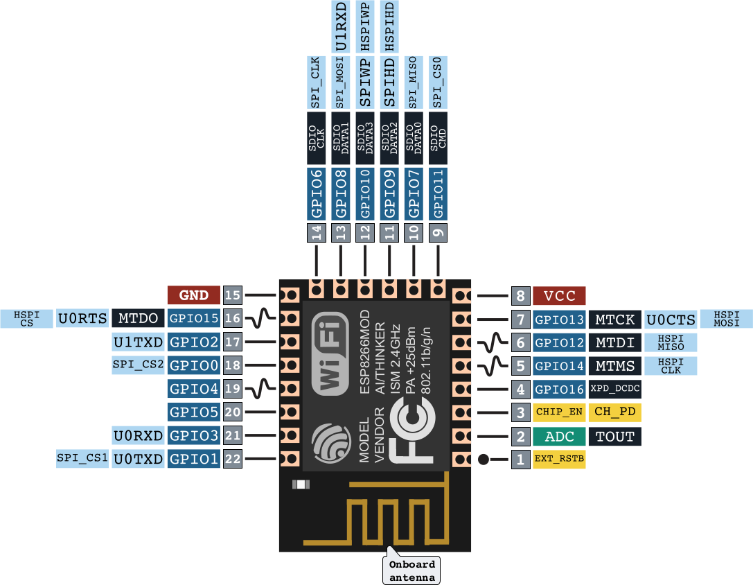
Unlike what you find on the Arduino, the pinouts on the PCB of the ESP-12E module are not very nicely organized for quickly connecting wires during prototyping. Unfortunately this mess often extends to the breakout boards too. For example, consider the pinout on my NodeMCU board:
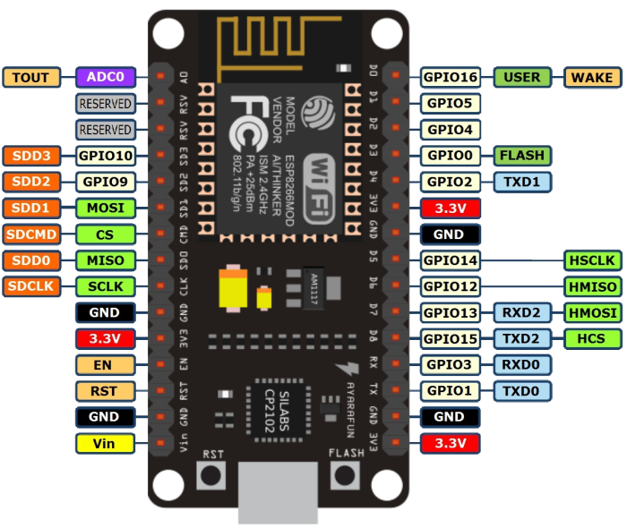
(Images taken from ESP8266 NodeMCU Arduino Killer)
Conclusions
Despite it’s poor documentation by Expressif, the ESP8266 is a really nice, inexpensive, board for IoT development with built-in WiFi. The community of support that has developed around the board on sites like esp8266.com, the Expressif BBS, and NodeMCU provide enough information that you can often get started developing IoT applications in a reasonable period of time.
Where to get for further information.
Here is a short list of resources which I found particularly useful when learning about the ESP8266:
- Kolban’s Book on ESP8266
- esp8266.com,
- NodeMCU
- NodeMCU board specification
- GeekcampSG, building wifi gadgets with the esp8266
- The Expressif BBS