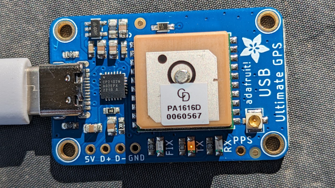
PPS and the Adafruit Ultimate GPS with USB-C
2023 Sep 09 - Brian Kloppenborg
While exploring methods to receive PPS signal over USB, I purchased the Adafruit Ultimate GPS with USB-C thinking that it offered everything I needed to receive the PPS signal over USB and route it to GPSD. Unfortunately, it doesn’t work as expected due to some not-so-easily discovered technical limitations. While researching things for this blog post, I also uncovered some information that provides some hope that this device may eventually work as expected.
Note: I’ve also linked to this post from the Adafruit forums hoping that someone there might pick up where I left off or perhaps that Adafruit will revise what is otherwise a very nice product.
What does the hardware provide?
The Adafruit Ultimate GPS with USB-C (2023 April 26 edition) has the following capabilities:
- GPS + GLONASS support with built-in antenna
- Ability to track 33 satellites and search for 99 satellites.
- -145 dBm acquisition and -165 dBm tracking sensitivity
- Multi-path detection and compensation
- -165 dBm sensitivity
- Built-in CP2012N A02 EPX 2210 A USB 2.0 to serial (UART) adapter. I think this is a variant of the CP2012N A02 QFN24 in the data sheet.
- PPS output on the Ring Indicator (RI) pin
- USB-C connector
As advertised, the PPS signal is indeed connected to the Ring Indiactor pin. This can be verified using the Python provided on the Adafruit Ultimate GPS FAQ:
brian@epislon:~$ sudo python3 pps-test.py
/dev/ttyUSB0
04,,,,,1.09,0.76,0.78*02
$GLGSA,A,3,79,71,80,73,69,,,,,,,,1.09,0.76,0.78*13
$GNRMC,015356.000,A,38XX.XXXX,N,104XX.XXXX,W,0.20,165.33,100923,,,A*62
$GNZDA,015356.000,10,09,2023,,*47
$GPGRS,015356.000,1,0.79,-33.6,-11.0,3.24,12.1,-0.88,-1.20,-7.27,0.73,3.30,4.48,4.23,*7C
$GPGST,015356.000,7.4,5.0,2.9,169.2,4.9,3.0,14*47

---------- Pulse low ----------

---------- Pulse high ----------
...
So what’s the issue?
On my Ubuntu 22.04 system with the 5.15.0-83-generic kernel there are two definitive issues and one speculative issue:
- Applications that attempt to set a
TIOCMIWAIT IOCTLon any of the handshake lines (e.g. Data Set Ready (DSR), Data Carrier Detect (DCD), Ring Indicator (RI), or Clear to Send (CTS)) will error out as follows:
sudo ppscheck /dev/ttyUSB0
# Seconds  nanoSecs   Signals
PPS ioctl(TIOCMIWAIT) failed: 25 Inappropriate ioctl for device
This is because the underlying cp210x driver in the Linux kernel does not
implement a usb_serial_driver.tiocmiwait function.
The driver does not have a method to poll the handshake lines that registers an IOCTL event. In other drivers, like
ftdi_sio, this is provided by ausb_serial_driver.process_read_urbfunction.There are claims (discussed below) that the hardware itself does not support the relevant interfaces; however, I find that somewhat unlikely because the datasheet claims that all relevant modem handshake signals are supported.
Prior works
I’m not the first person to spot this issue. While doing some research for this
blog post, I found a thread started by Adafruit Forum user bjmcculloch who
noted an identical issue
with the previous version of the GPS module that used a CP2104 chip.
Likewise, Silicon Labs forum user D444540130 wrote that
events on the DCD pin are delayed
on the cp210x family of converters until the GPS receiver sends additional data.
There are also two patches to the cp210x Linux driver that provide some
additional information about the problem.
In the notes for a patch that
added support for line-status events
it is claimed that the device’s event-insertion mode doesn’t work as expected on the CP2102.
Likewise, a subsequent patch that
added support for TIOCGICOUNT
claims that modem status events are buffered and can’t be used to implement
TIOCMIWAIT commands.
What is the underlying problem?
A review of the usb_serial_driver structure
The Linux Kernel defines the usb_serial_driver structure in
include/linux/usb/serial.h.
This structure permits device drivers to provide specific functionality.
The
usb-serial.c
provides several default implementations of various functions which can be used
by driver developers as needed.
To figure out what functions might need to be implemented, I compared the ftdi_sio.c (which provides a PPS signal), with that of cp210x.c. This becomes important in later portions of this post.
Investigating the usb_serial_driver.tiocmiwait function
First, lets address the issue with TIOCMIWAIT IOCTL. The error emanating from
ppscheck comes from either
the mutability
or gpds
repository
depending on your upstream repository. In both cases, the code is attempting
to set an IOCTL on the device and the error indicates that the function
fails. This is because the driver does not implement the
usb_serial_driver.tiocmiwait. In the case of the ftdi_sio.c driver, they
simply point to the default usb_serial_generic_tiocmiwait function, so
that is likely adequate in our situation. Updating cp210x.c to have this
function pointer as follows:
static struct usb_serial_driver cp210x_device
...
    .tiocmiwait =		usb_serial_generic_tiocmiwait,
...
does indeed resolve the issue; however, a PPS signal never arrives.
We also need the usb_serial_driver.process_read_urb function
While skimming the ftdi_sio driver, I also noticed that their
ftdi_process_packet has code that checks the status of the handshake lines.
This code is called from one location, the ftdi_process_read_urb function
which is pointed to by the usb_serial_driver.process_read_urb function
pointer. Reading through the
ftdi_sio.h
file, it appear that the handshake lines are stored in registers in the device.
Figuring this out for the CP2012N will require more knowledge of the device
than what I’ve found in the
corresponding data sheets.
So I can’t add this functionality myself.
A newfound hope
After getting to this point, I thought it was a done deal; however, I found a
custom cp210x driver by Fortian Inc.
Said driver claims to provide a PPS signals from a Jackson Labs “Firefly” GPS
Disciplined Oscillator over an unspecified cp210x device.
Looking at that code, they are able to detect and register a DCD change by checking the value of specific device registers (see here). Unfortunately, there aren’t any breadcrumbs there for me to follow to identify where they discovered the register values.
Resolving the issue
See my next post on fixing the driver
