Helical Antenna Construction
2004 Aug 01 - Brian Kloppenborg
Basic Information
The Helical antenna is a simple way of obtaining high-gain and a broad band of frequency characteristics. A helical antenna radiates when the circumference of the helix is of the order of one wavelength and radiation along the axis of the helix is found to be the strongest. This antenna is mainly directional. The radiation from a Helical antenna is circularly polarized, that is to say that the Electromagnetic field rotates about the axis of the helix in the direction of the helix turn. Therefore, the radiation is either circularly polarized clockwise or counter-clockwise.
If one were to explore the field from a Helical antenna in the direction of maximum radiation with a simple monopole or dipole antenna, one should find that the strength of the signal will remain the same as long as the dipole is perpendicular to the axis of the Helix. On the side of a Helical antenna, the field is elliptically polarized. Therefore, the horizontal and vertical portions of the signal will not be of equal proportions.
When using Helical Antennas it is very important to make sure that both antennas have the same thread orientation (i.e.. both clockwise) otherwise the received signal will be significantly decreased.
There are at least two good methods for constructing a Helical antenna the first of which is documented in VHF-UHF Manual D.S. Evans (G3RPE) and G.R. Jessop (G6JP) Third Edition printed by RSGP in 1977. Although this is a old book, its design ideas are very quick, easy and strong. They suggest to pre-drill a boom made out of something that is “sufficiently rigid to adequately support the whole structure, and at the same time be of a non-metallic material such as wood, thick-wall plastic tube, or thick-wall fiberglass.”
The VHF-UHF Manual gives a table for design construction (λ is the wavelength):
| Frequency | Dimensions | ||||
|---|---|---|---|---|---|
| "D" | "R" | "P" | "a" | "d" | |
| General | 0.32 | 0.8 | 0.22 | 0.12 | |
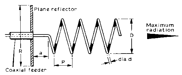
The dimensions are based on the following diagram, again from the VHF-UHF Manual

The original caption read as follows: The helical aerial. The plane reflector may take the form of a dartboard type of wire grid. The dimensions given in the table are based on a pitch angle of 12. The helix, which may be wound of copper tube or wire the actual diameter of which is not critical, must be supported by low-loss insulators.
I should emphasize the last phrase “low loss insulator”. As it turns out, if the dialectic constant of the supporting mechanism is too high, the waveform that enters the helix is highly deformed and may not be within the bandwidth of the helix antenna.
They also list the following table:
| Turns | 6 | 8 | 10 | 12 | 20 |
|---|---|---|---|---|---|
| Gain | 12dB | 14dB | 15dB | 16dB | 17dB |
| Beam width | 47 | 41 | 36 | 31 | 24 |
The approximate bandwidth for a Helical antenna is given by the following formula:
Bandwidth = 0.75 * λ to 1.3 * λ
I was unable to surmise how this relationship is derived, unless it is directly related to the number of coils. One must also consider input impedance when they design their own Helical antenna. In general the input impedance is:
Feed impedance = 140 * (circumference) / (λ * Ω)
Also, the beam width is:
Beam width (in degrees )= (12,300/ (# of turns))
##Construction Method 1 (VHF-UHF Manual)
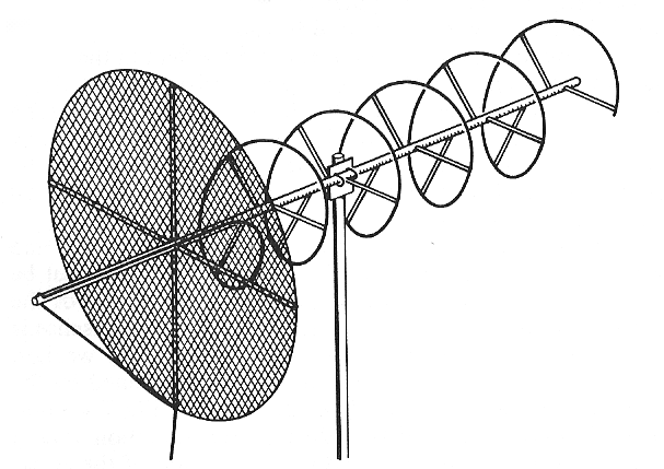
Unfortunately, I have yet to build an helix antenna according to the diagram in the VHF-UHF manual. Therefore, I can only offer the diagram in the text:

I can however, offer a few suggestions:
First off, whatever you use for a center support, make sure it is not metal and, if you are using plastic or PVC, check to see if the dialectic constant is small. If you choose to use PVC or CPVC, try to use PVC. The dialectic constant for PVC is smaller than that of CPVC. Also, minimize the amount of PVC that you use. As will be noted in the next construction method, using too much PVC can slew your signal and cause your antenna to not operate at the proper frequency.
Secondly, the supports for the coil should not be made of metal. Use a good insulator with a low dialectic constant. I would suggest wooden dowels.
Thirdly, the reflector should either be solid, or made of a mesh which has holes no greater than 1/32 to 1/125 for optimum reception, however; one may use something like metal lath (commonly used to put stucco on buildings) or a heavy window screen and not see a significant degradation in signal quality. Whatever you use, make sure it has a high electrical conductivity.
Finally, run the feed wire as in the diagram above. That is behind the reflector and then through the center of the reflector. Also, the outside sheath of your cable should be connected directly to the reflector, and the center conductor connected to the coil.